Source to target mapping что это
What is Source-to-Target Mapping?
Source-to-Target mapping is a set of data transformation instructions that determine how to convert the structure and content of data in the source system to the structure and content needed in the target system. Source-to-Target Mapping solutions enable their users to identify columns or keys in the source system and point them to columns or keys in the target systems. Additionally, users can map data values in the source system to the range of values in the target system.
Source-to-target mapping in Travel and Hospitality
Travel aggregators collect data from numerous parties, including airlines, car rental companies, hotel chains, and more. The data they ingest varies markedly from one source to another. Each hotel chain, for example, describes its properties and rooms in each property using different columns and values. To ensure that consumers can easily search and browse through available inventory, travel aggregators must map the data they ingest to their common data format.
Source-to-target mapping in Retail
Electronic Data Interchange (EDI) files are a well-accepted mechanism to exchange data between suppliers and their retailer partners. Product Activity Data (EDI 852), Purchase Orders (EDI 850), advanced ship notices (EDI 856), and other types of EDI files help suppliers exchange data electronically and consistently. This helps all parties save time and operational costs, reduce inventory levels, and respond faster to supply and demand changes. Source-to-Target Mapping would involve parsing EDI files and mapping their content to one common data format, such as a schema of a CSV file.
Recent Posts
Categories
About Source to Target (S2T) Document or Mapping Document
S2T document is the bible of any ETL Projects. This will be designed by the Data Modeler’s using the FSD’s (Functional Specification Documents).
Data Modeler’s are interested in
Most of the S2T’s are written in Excel spread sheet. Where you will find many columns, each column is important for the ETL Load to be designed.
Major components of an S2T,
using the Version Numbers.
SourceDatabase– Source Database name or names will be mentioned in this space
Source Column– All the Source columns from respective Source Database are mentioned in this space (these columns will undergo the transformations if required.
Extraction Criteria– As I already mentioned, we are not going to pull all the data from the source before transformation however we need to pull the data that we required for the transformation and this will be mentioned in this space. All the Joins and Unions will be done here so as a Tester we need to understand and analysis this area with more care.
Example – Now I wanted to load Customers details and their balance from Savings account. Customers Details will be fetched from Cust_Detl table and the Balance from ACCT_BALANCE table, so you need to perform join in between. This extracting filters only Customers Savings account. So I consider this is my Data extraction criteria.
Filter Criteria– After we extracted the data from the source we need to filter the data if required for few or more target tables and this will be covered in this space.
Target Database – Target Database name or names will be mentioned in this space
Target Column – All the Target columns from respective Target Database are mentioned in this space (these columns will undergo the transformations if required.
Key or Value Columns–Next to the Target Column names you could see Key / Value. Key column means the column that makes the record unique and Value means, what makes the record time variant.
Comments and Version Changes – This space will explain us what was in the S2T before and what changed now. Comments will tell us more about the transformation.
What we need to look in the S2T?
As soon as you get the S2T, please query your Staging Source tables and check the data that you have got will satisfy your transformation rule. S2T’s will be written with the SIT phase data, and the rules mentioned might change as soon as we get the UAT Phase data. So to achieve the good quality of testing we always interested in UAT data.
Most of us will confuse the below transformation logic
Example: If the source columns are NOT NULL BLANK SPACE 0 and DO NOT LOAD the record. In this case, we might look for the record in the target when it has Unknown values.
Thanks for reading – Comments are Expected 🙂
Source Maps: быстро и понятно
Механизм Source Maps используется для отображения исходных текстов программы на сгенерированные на их основе скрипты. Несмотря на то, что тема не нова и по ней уже написан ряд статей (например эта, эта и эта) некоторые аспекты все же нуждаются в прояснении. Представляемая статья представляет собой попытку упорядочить и систематизировать все, что известно по данной теме в краткой и доступной форме.
В статье Source Maps рассматриваются применительно к клиентской разработке в среде популярных браузеров (на примере, DevTools Google Chrome), хотя область их применения не привязана к какому-либо конкретному языку или среде. Главным источникам по Source Maps является, конечно, стандарт, хотя он до сих пор не принят (статус — proposal), но, тем не менее, широко поддерживается браузерами.
Работа над Source Maps была начата в конце нулевых, первая версия была создана для плагина Firebug Closure Inspector. Вторая версия вышла в 2010 и содержала изменения в части сокращения размера map-файла. Третья версия разработана в рамках сотрудничества Google и Mozilla и предложена в 2011 (последняя редакция в 2013).
В настоящее время в среде клиентской разработки сложилась ситуация, когда исходный код почти никогда не интегрируется на веб-страницу непосредственно, но проходит перед этим различные стадии обработки: минификацию, оптимизацию, конкатенацию, более того, сам исходный код может быть написан на языках требующих транспиляции. В таком случае, для целей отладки необходим механизм позволяющий наблюдать в дебаггере именно исходный, человекочитаемый код.
Для работы Source Maps необходимы следующие файлы:
Map-файл
Вся работа Source Maps основана на map-файле, который может выглядеть, например, так:
Обычно, имя map-файла складывается из имени скрипта, к которому он относится, с добавлением расширения «.map», bundle.js — bundle.js.map. Это обычный json-файл со следующими полями:
Загрузка Source Maps
Для того, чтобы браузер загрузил map-файл может быть использован один из следующих способов:
Таким образом, загрузив map-файл браузер подтянет и исходники из поля «sources» и с помощью данных в поле «mappings» отобразит их на сгенерированный скрипт. Во вкладке Sources DevTools можно будет найти оба варианта.
Для указания пути может использоваться пседопротокол file://. Также, в может быть включено все содержимое map-файла в кодировке Base64. В терминологии Webpack подобные Source Maps названы inline source maps.
Self-contained map-файлы
Код файлов-исходников можно включить непосредственно в map-файл в поле «sourcesContent», при наличии этого поля необходимость в их отдельной загрузке отпадает. В этом случае названия файлов в «sources» не отражают их реального адреса и могут быть совершенно произвольными. Именно поэтому, вы можете видеть во вкладке Sources DevTools такие странные «протоколы»: webpack://, ng:// и т.д
Mappings
Сущность механизма отображения состоит в том, что координаты (строка/столбец) имен переменных и функций в сгенерированном файле отображаются на координаты в соотвествующем файле исходного кода. Для работы механизма отображения необходима следующая информация:
(#1) номер строки в сгенерированном файле;
(#2) номер столбца в сгенерированном файле;
(#3) индекс исходника в «sources»;
(#4) номер строки исходника;
(#5) номер столбца исходника;
Все эти данные находятся в поле «mappings», значение которого — длинная строка с особой структурой и значениями закодированными в Base64 VLQ.
Строка разделена точками с запятой (;) на разделы, соответствующие строкам в сгенерированном файле (#1).
Каждый раздел разделен запятыми (,) на сегменты, каждый из которых может содержать 1,4 или 5 значений:
Каждое значение представляет собой число в формате Base64 VLQ. VLQ (Variable-length quantity) представляет собой принцип кодирования сколь угодно большого числа с помощью произвольного числа двоичных блоков фиксированной длины.
В Source Maps используются шестибитные блоки, которые следуют в порядке от младшей части числа к старшей. Старший 6-й бит каждого блока (continuation bit) зарезервирован, если он установлен, то за текущим следует следующий блок относящийся к этому же числу, если сброшен — последовательность завершена.
Поскольку в Source Maps значение должно иметь знак, для него также зарезервирован младший 1-бит (sign bit), но только в первом блоке последовательности. Как и ожидается, установленный sign бит означает отрицательное число.
Таким образом, если число можно закодировать единственным блоком, оно не может быть по модулю больше 15 (11112), так как в первом шестибитном блоке последовательности два бита зарезервированы: continuation бит всегда будет сброшен, sign бит будет установлен в зависимости от знака числа.
Шестибитные блоки VLQ отображаются на кодировку Base64, где каждой шестибитной последовательности соответствует определенный символ ASCII.
Декодируем число mE. Инверсируем порядок, младшая часть последняя — Em. Декодируем числа из Base64: E — 000100, m — 100110. В первом отбрасываем старший continuation бит и два лидирующих нуля — 100. Во втором отбрасываем старший continuation и младший sign биты (sign бит сброшен — число положительное) — 0011. В итоге получаем 100 00112, что соответствует десятичному 67.
Можно и в обратную сторону, закодируем 41. Его двоичный код 1010012, разбиваем на два блока: старшая часть — 10, младшая часть (всегда 4-битная) — 1001. К старшей части добавляем старший continuation бит (сброшен) и три лидирующих нуля — 000010. К младшей части добавляем старший continuation бит (установлен) и младший sign бит (сброшен — число положительное) — 110010. Кодируем числа в Base64: 000010 — C, 110010 — y. Инверсируем порядок и, в итоге, получаем yC.
Для работы с VLQ весьма полезна одноименная библиотека.
Source to Target Mapping: A Comprehensive Guide
Do you wish to understand Source to Target Mapping? Are you confused about whether manual or automated Source to Target mapping would be better for your data transfer requirements? If yes, then you’ve come to the right place. This article will provide you with an in-depth understanding of how Source to Target Mapping works and how you can make the right choice on how your data should be mapped to your target system.
Table of Contents
Understanding Source to Target Mapping in Data Warehouses
When moving data from one system to another, it’s almost impossible to have a situation where the source and the target system have the same schema. Hence, there is a need for a mechanism that allows users to map their attributes in the source system to attributes in the target system. However, this process becomes more complicated than it already is when there is data that has to be moved to a central data warehouse from various data sources, each having different schemas.
Source to Target mapping can be defined as a set of instructions that define how the structure and content in a source system would be transferred and stored in the target system.
It can be seen as guidelines for the ETL (Extract, Transform, Load) process that describes how two similar datasets intersect and how new, duplicate and conflicting data is processed. It also sets various instructions on dealing with multiple data types, unknown members and default values, foreign key relationships, metadata, etc.
To understand how Source to Target Mapping works, an example is shown below considering a small database of various movies and actors.

The above image shows three tables, two of which are a list of movies and actors and a third table defining a relationship between those two tables. The “movieid” and “actorid” attributes in the “casting” table are foreign keys to the “id” attribute in the “movie” table and the “id” attribute in the actor table, respectively. It can be observed that these tables are in the normalized form.
If this data has to be moved to a data warehouse, various complex operations will have to be performed. This database will have to be denormalized so that no complex join operations have to be performed on the large datasets at the time of analysis.
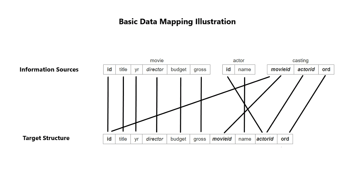
The above image shows how the data would be ideally stored in the data warehouse. This would require each attribute in the source to be mapped to each attribute in the target structure before the data transfer process begins. This was a fundamental example, and real-world situations can become much more complicated than this based on the following factors:
Understanding the Need to Set Up Source to Target Mapping
Source to Target mapping is an integral part of the data management process. Before any analysis can be performed on the data, it must be homogenized and mapped correctly. Unmapped or poorly mapped data might lead to incorrect or partial insights.
Source to Target Mapping assists in three processes of the ETL pipeline:
Data Integration
Data integration can be defined as the process of regularly moving data from one system to another. In most cases, this movement of data is from the operational database to the data warehouse.
The mapping defines how data sources are to be connected with the data warehouse during data integration. It sets various instructions on how multiple data sources intersect with each other based on some common information, which data record is preferred if duplicate data is found, etc.
Data Migration
Data migration can be defined as the movement of data from one system to another performed as a one-time process. In most cases, it is done to ensure that multiple systems have a copy of the same data. Although it increases the storage requirements for the same data, it makes it more available and reduces the load on a single system. The first step of data migration is data mapping in which attributes in the data source are mapped to attributes in the destination.
Data Transformation
Data transformation can be defined as the conversion of data at the source system to a format required by the destination system. This includes various operations such as data type transformation, handling missing data, data aggregation, etc. The first step in data transformation is also mapping that defines how to map, modify, join, filter, or aggregate data as required by the destination system.
Steps Involved in Source to Target Mapping
You can map your data from a source of your choice to your desired destination by implementing the following steps:
Step 1: Defining the Attributes
Before data transfer between the source and the destination begins, the data to be transferred has to be defined. This means defining which tables and which attributes in those tables are to be transferred. If data integration is being performed, the frequency of integration is also defined in this step.
Step 2: Mapping the Attributes
Once the data to be transferred has been defined, it has to be mapped according to the destination system’s attributes. If the data is being integrated into a data warehouse, some amount of denormalization would be required, and hence, the mapping would be complex and error-prone.
Step 3: Transforming the Data
This step involves converting the data in a form suitable to be stored in the destination system and homogenized to maintain uniformity.
Step 4: Testing the Mapping Process
Once the first three steps have been completed, it has to be tested on some sample data sources to ensure that the right data attributes in the proper form are mapped correctly with the destination system.
Step 5: Deploying the Mapping Process
Upon completion of testing and successful data transfer, migration or integration can be scheduled on the live data as per the user’s requirements.
Step 6: Maintaining the Mapping Process
This step is only required for data integration since migration is a one-time process. Data integration will take place regularly after certain intervals of time. Hence, the Source to Target Mapping process must be maintained and updated periodically to handle large datasets and any new data sources if required.
Simplify ETL with Hevo’s No-code Data Pipelines
Hevo offers a fully managed solution for your fully automated pipeline to set up data integration from 100+ data sources and will let you directly load data to your data warehouse. It will automate your data flow in minutes without writing any line of code. Its fault-tolerant architecture makes sure that your data is secure and consistent. Hevo provides you with a truly efficient and fully automated solution to manage data in real-time and always have analysis-ready data.
You are simply required to enter the corresponding credentials to implement this fully automated data pipeline without using any code.
Let’s look at some salient features of Hevo
Source to Target Mapping Techniques
The two primary techniques for mapping are as follows:
Manual Source to Target Mapping
This method requires developers to manually code the connection between the source and the destination system. This process can only be used in case the mapping is to be performed for only a few sources that don’t have much data.
Advantages:
Disadvantages:
Automated Source to Target Mapping
If the data is being integrated into a data warehouse, the number of sources and the volume of data will increase with each round of data transfer. A manual mapping mechanism would be too complex and expensive to manage in this scenario, and an automated mapping system would be required. This system should be able to scale up or down as per the requirements of the data to be transferred.
Advantages:
Disadvantages:
Simplify Schema Mapping Using Hevo’s Automated Schema Mapper
Businesses can choose to make their own in-house mapping automation tools. However, this would require a separate engineering team that would first develop the tool and then maintain it as new data sources are added. This will not only be time-consuming but also very expensive for any business. It would cost the businesses much less if they use an existing tool like Hevo to fulfil all their requirements.
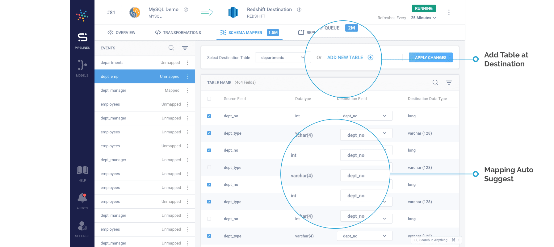
Hevo is a No-code Data Pipeline. It supports pre-built data integrations from 100+ data sources. It provides automated schema mapping that intelligently infers the schema of incoming data once it is connected to the data source and suggests a schema for the destination data warehouse integrating all sources. The user can choose to accept the suggestion or make any changes on their own.
More information on Hevo’s automated schema mapping can be found here.
Conclusion
This article provides an in-depth understanding of how Source to Target Mapping works, why it’s necessary, what steps are involved in it, and the various methods of mapping, allowing users to decide how they want to perform mapping for their systems. The user can either choose to manually map the data, which is error-prone and extremely complicated or automate the process using Hevo.
Sign Up for a 14-day free trial and experience the feature-rich Hevo suite first hand. Have a look at our unbeatable pricing here, which will help you choose the right plan for you.
6
Defining Source to Target Mappings
The following three chapters describe how to map data sources to targets. This chapter describes how to create and update mapping definitions. It also describes the Warehouse Builder Mapping Editor. The next chapter describes how to add operators and transformations to a mapping. The following chapter describes how to configure the logical and physical properties of a mapping, how to reconcile mapping operators with repository objects, and how to validate and generate the PL/SQL code used for deployment.
This chapter includes the following topics:
Understanding Warehouse Builder Mappings
A mapping describes a series of operations that pulls data from sources, transforms it, and loads it into targets. When you create a mapping, you use operators to define the Extraction, Transformation, and Loading (ETL) operations that move data from a source object to a data warehouse target object. Mappings provide a visual representation of the flow of the data from sources to targets and the operations performed on the data. Define mappings using the Mapping Editor, Property Inspectors, Expression Builder, and Code Editor.
About Mapping Operators
All mappings are based on mapping operators. A mapping operator is a logical representation of a physical repository object. A mapping operator contains row sets. A row set is any set of zero or more rows of structured data brought into or emerging from a mapping operator. A row is the basic unit of data in a mapping. The number of rows in a row set is the cardinality of that row set.
A mapping operator defines how input row sets are manipulated to produce output row sets. A mapping operator can alter the cardinality of row sets. Warehouse Builder contains several mapping operators, each with its own purpose for processing row sets.
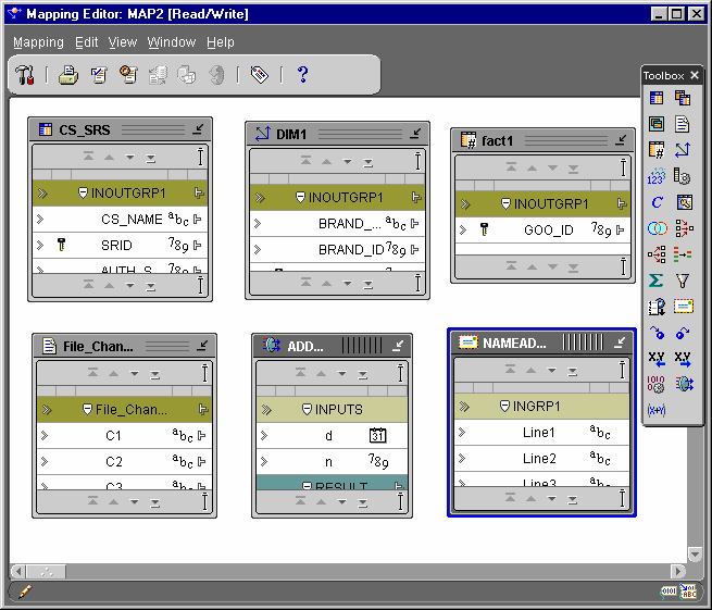
You define and edit mapping operators using the Mapping Editor and Property Sheets. The Mapping Editor contains a toolbox that visually represents the operators.
The operator types available within the Mapping Editor include:
About Operator Properties
To specify the purpose of an operator, edit the property inspector for the operator. You can set properties at the following levels:
About Attributes and Attribute Groups
Attributes are inputs and outputs for operators. Attributes belong to attribute groups. The group type determines the attribute type. An attribute group type can be an:
Attribute and attribute group names are logical. Although the attribute names of the target object are often the same as the logical attribute names of the operator, their properties remain independent of the attributes of the operator to which they are connected. This protects any expression or use of an attribute from corruption if it is manipulated within the operator. You can rename attribute groups and attributes independent of their sources. The cardinality of attribute groups must match in order to be used in the same input group.
About Display Sets
A display set is a graphical representation of a group of operator attributes. By default, the All display set displays for all attribute groups. If an attribute group contains more than one display set, then you can select a different display set from the list on the View menu. You can define display sets for an attribute group in the mapping editor, or they can be inherited from the attribute sets of a warehouse object that are defined during the source and target definition phase of data warehouse design. See «Creating Attribute Sets» for information on attribute sets.
You can see only one display set at a time for an attribute group. By default, the Mapping canvas shows the display sets with all the attributes in the respective attribute groups. You can edit display sets and define new display sets for an operator in the Mapping Editor. See «Editing Operator Attributes» for more information.
Table 6-1 describes the default attribute sets for Display Sets.
Table 6-1 The Default Attribute Sets
This is the default attribute set and includes all attributes.
About Binding Mapping Operators
Mapping operators are independent from the repository objects they represent. When you bind a mapping operator to a repository object, you create a link between them. This link causes the operator to inherit the attributes and attribute sets of the repository object.
The Mapping Editor generates a default logical name for operators, which you can change at any time. Editing of bound operators is limited to changing the logical name and adding new attributes to the operator. Editing has no effect on the attributes of the physical repository object.
If you choose to leave an operator unbound, it generates code that does not affect any repository object. You must bind the mapping operator to a repository object in order for the code to affect the repository object. After you bind a mapping object to a repository object, it cannot be unbound.
Defining Mappings
The first part of this section describes the Warehouse Builder Mapping Editor. The remainder of this section describes how to define a mapping.
About the Mapping Editor
The Mapping Editor is the interface for defining what you want to transform and map. The mapping editor uses an operator for each operation you want to perform. A series of operations defines a mapping.
The Mapping Editor includes:
Figure 6-1 Mapping Editor Toolbar and Menu
Figure 6-2 Toolbox
Figure 6-3 Mapping Editor Canvas Showing Mapping Operators
When you open the property inspector, you can select another operator, attribute, or attribute group and the property inspector displays the property for the selected object. Only one property inspector can be open at a time.
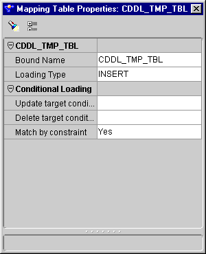
Figure 6-4 Operator Property Inspector
If no operator, attribute group, or attribute is selected while a property inspector is open, the property inspector shows an empty list.
Creating a Mmapping
When you define a mapping object, you create a container that holds the mapping operators defining the ETL process. Use the Mapping Editor to define a mapping by:
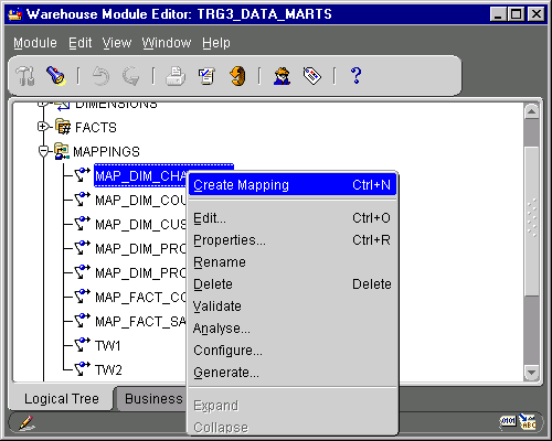
To create a mapping object:
Figure 6-5 Warehouse Module Editor
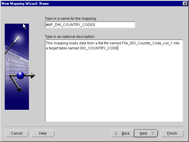
Warehouse Builder opens the New Mapping Wizard.
The New Mapping Wizard displays the Name page.
Figure 6-6 New Mapping Wizard Name Page
The New Mapping Wizard displays the Finish page. Verify the name of your new mapping.
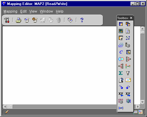
Warehouse Builder stores the definition for the mapping and inserts its name in the warehouse module navigation tree. The Mapping Editor opens.
Figure 6-7 Mapping Editor
Displaying the Mapping Editor
Use the Mapping Editor to define ETL operations. Open the Mapping Editor from the Warehouse Module Editor.
To display the Mapping Editor, do one of the following:
Selecting Data Operators
You can use a data operator as a data source or data target. Data operators include Mapping Tables, Mapping Dimensions, Mapping Facts, Mapping Views, and Mapping Materialized Views. Follow the same steps when you select any of these operators.
You can connect any data operator to any other mapping operator. A data operator generates a PL/SQL mapping.
To select a table operator:
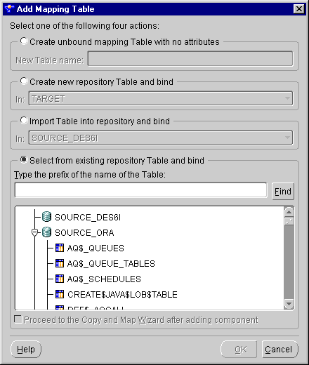
The Add Mapping Table dialog displays.
Figure 6-8 Add Mapping Table Dialog
If you make this selection and click OK and have already defined a database link for the module from which you are importing the object, then Warehouse Builder returns the Database Link Information dialog. Enter the appropriate information in the dialog. If you have not defined a database link, then Warehouse Builder displays the New Database Link Information dialog. See «Configuring Connection Information for Database Sources» for information on how to define a new database link.
To select multiple items, hold down the Control key as you click each item. To select a group of items located in a series, click the first object in your selection range, hold down the Shift key, and then click the last object.
If you are selecting a Mapping Fact, a Mapping Dimension, or a Key Lookup operator, then you have two choices:
You do not have the option to import an object if you are selecting a Mapping View or a Mapping Materialized View operator.
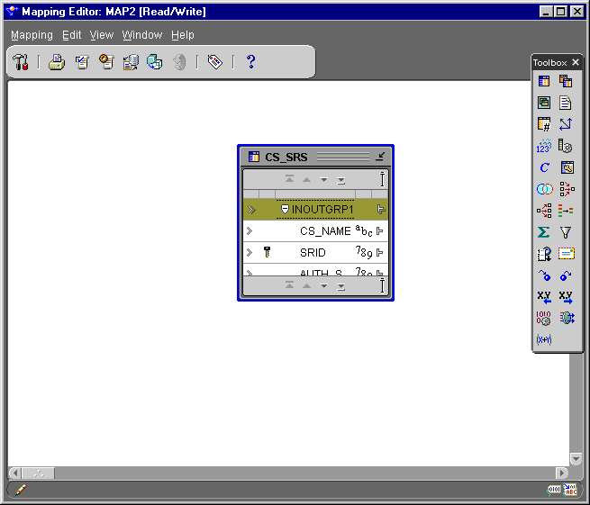
A Mapping Table operator displays on the canvas. This operator shows the names and attributes of the table to which it is bound.
Figure 6-9 Mapping Editor Showing a Mapping Table Operator Source
Selecting a Flat File Operator
You can use a Mapping Flat File operator as a data source or data target. As a data source, the Mapping Flat File operator acts as the row set generator for reading from a flat file.
To use a flat file as a target, a file source module must exist and it must contain valid flat files. A mapping to a flat file target generates a PL/SQL package that is spooled into a flat file instead of loading data into rows in a table. When you define a Mapping Flat File operator as a target, you are using an existing file as a template for the target flat file. Warehouse Builder comes with a file source module called TARGET_FILES for use as a template. This module contains a comma-delimited file (CSV_FILE) and a fixed-length file (FIXED_LENGTH_FILE), and each file contains ten fields of the CHAR data type.
A mapping can contain up to 50 flat files as targets, and it can also contain a mix of flat files, relational objects, and transformations. You can connect a Mapping Flat File source operator to any other operator except another Mapping Flat File operator.
You have the following two options for a Mapping Flat File Operator:
Selecting an SAP Source
The following section describes how to select an SAP operator as a source for a mapping. An SAP operator used as a source can be connected to Mapping Table, Mapping Dimension, and Mapping Fact operators. You can generate ABAP or PL/SQL code for your mappings. If you generate ABAP code, only the Filter and Joiner operators are available.
To select an SAP source:
The Add Mapping Table dialog displays.
The field at the bottom of the dialog displays a list of SAP tables whose definitions were previously imported into the SAP source module.
The editor places a mapping table on the mapping canvas to represent the SAP table.
When you select an SAP operator as a source, the option to Proceed to the Copy and Map wizard after adding component is enabled. If you check this option and click OK, Warehouse Builder displays the Copy and Map Wizard.
The Copy and Map wizard enables you to perform three functions: copy the selected source object, create a target object based on the source object definitions, and map the source object to the new target object. The Copy and Map option is only available when you select a single table as a source.
To use the Copy and Map Wizard:
The Copy and Map Wizard Welcome page displays.
The Target Name page displays.
If the repository already contains an object with the same name, a name conflict error message displays. You must then rename the object you are creating.
The Source Columns page displays.
The fields on this page are read-only. By default, this page displays and selects all columns defined within the source table. To deselect a column, uncheck the selection check box next to that column. Click Select All to copy all the columns within the table. Click Deselect All to deselect all the columns within the table. You must select at least one column to copy.
The Target Columns page displays. You use this page to customize the selected columns or add new ones to your target table. The first two columns within the table display the physical and logical names of the columns. You cannot modify the logical names, you can only modify the physical names of a column. The default physical names are copied from the source physical names.
Edit the following fields:
Click Add to add a new column within your target object. The Remove option is only enabled for columns you create. If you do not want to copy a column defined in the source object, click Back to return to the Source Columns page and deselect the column.
If you rename a target column, then the new name is preserved regardless of how you choose to generate the target physical name. For example, the source physical name of a table is MANDT and its logical name is MANDT_Client. If you change the default target physical name from MANDT to MANDT_Client_Name, then this name is preserved.
If the new name is not unique, a name conflict error message displays. Click OK to rename the column automatically or click Cancel to rename it yourself.
The Summary and Copy page displays. Verify the information on this page.
The Mapping Editor displays the source table mapped to the newly created target table. You can locate this bound target table under the TABLES node in the Warehouse Module Editor.
Selecting a Data Flow Operator
You can add operators that alter the source data as it flows to the data targets. Warehouse Builder includes data flow operators in the Toolbox. You can create custom operators using the Oracle Transformation Library or Expression Builder. See «Using Expression Builder» for information on creating custom operators.
To select a data flow operator, drag a data flow operator from the Toolbox and drop it onto the Mapping Editor canvas. After you make your selections, a data flow operator displays on the canvas. Each data flow operator requires a different set of tasks when you add them to a mapping. Chapter 7, «Using Mapping Operators and Transformations» describes the flow operators and how to add them to a mapping.
Connecting Mapping Operators
After you have defined mapping source operators, data flow operators, and target operators, you are ready to connect them. You can connect individual operator attributes to each other, or you can connect attribute groups. When you connect groups, you can control which attributes are connected using the Auto-Mapping dialog.
To connect mapping operators, do one of the following:
The position of the attribute where you start your mapping and the position where you release the mouse button determines the type of data flow connections you make in the mapping. If the mouse button is released over an invalid target, no data flow connection is established.
You cannot create the following links:
Connecting Attributes
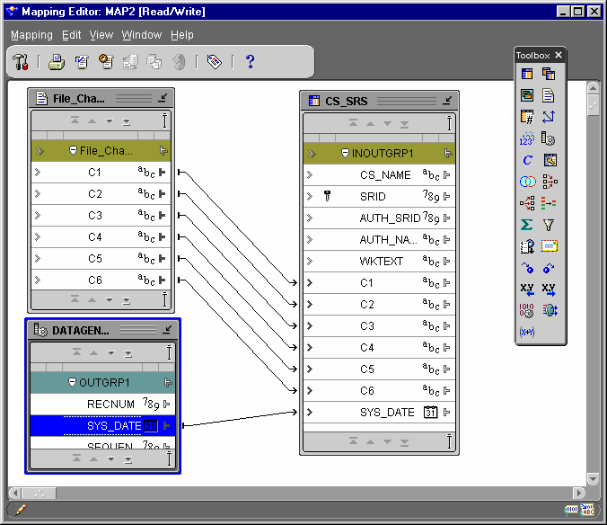
To connect mapping operator attributes, draw lines from output attributes or output attribute groups to input attributes or groups between the operators. These lines are data flow connections. The data flow connections graphically represent how the data flows from a source to a target.
To connect operators:
As you drag the mouse, a line appears on the Mapping Editor canvas to indicate a connection.
Figure 6-10 Connected Operators in a Mapping
Repeat steps one through three until you have created all the data flow connections appropriate for your situation.
Connecting Attribute Groups
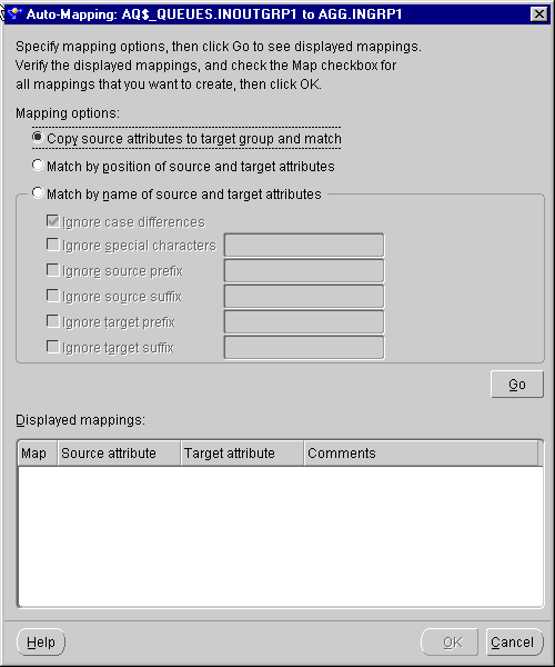
If you connect source attributes to target attribute groups, Warehouse Builder opens the Auto-Mapping dialog. Auto-mapping enables you to specify a rule that Warehouse Builder uses to automatically map source attributes to target attributes. After you specify Auto-Mapping options, Warehouse Builder creates the mapping.
Figure 6-11 Auto-Mapping Dialog
The Auto-Mapping dialog displays matching criteria and a panel that displays the mappings. Choose the match criteria by selecting:
Copy: Copies source attributes to the target group and creates mappings from the source attributes to the new target attributes.
You cannot copy source attributes to dimension or fact targets.
Match by Position: Creates mappings between existing attributes based on the position of the attributes in their respective groups. Source and target attributes are matched in order, until all attributes for a target are matched. If a source operator contains more attributes than a target, then the remaining source attributes do not map to a target.
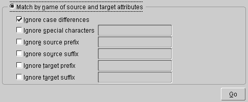
Match by Name: Creates mappings between existing attributes with matching names. By selecting from the list of options, you can specify auto-mapping between names that do not match exactly. You can combine these options:
Figure 6-12 Match by Name Matching Options
After you set the matching criteria, click Go.
If you attempt to map a source attribute group with no attributes, or if you are matching by name and there are no matches, an error dialog displays.
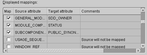
If one or more of the attributes can be matched, the Displayed Mappings field displays the matches. You can verify and change the mappings before they are implemented.
Figure 6-13 Displayed Mappings Field
The check boxes for each attribute enable you to include or exclude attributes in a mapping. The source column lists the source attributes and the target column lists the matching target attributes. The comments column contains information about the results from your matching criteria. For example:
Target was already mapped: A target attribute can have only one mapping from one source attribute. The check box is unchecked and appears grayed out to indicate that the mapping will not be created.
Target may not be double-mapped: If name matching finds multiple matches to a target attribute, only one mapping can be created. The check box for the first mapping is checked, and all other mappings to that target attribute are unchecked. You can select only one check box. Selecting one attribute deselects any other attribute.
Source may be double-mapped: A source attribute can be mapped to different target attributes. If name matching finds multiple matches from a source attribute, all of these mappings can be created. You can then deselect the target attributes that you do not want to map to by clicking their check boxes.
Source will not be mapped: No target attributes are available for the source.
Target will not be mapped: No source attributes are available for the target.
Click OK to create the mapping.
If you open the Auto-Mapping dialog while the mapping editor is in read-only mode, an error displays. You must have read-write permission before you can use auto-mapping. See «About Multi-User Access» for more information on read-write permissions.
To complete the mapping, you may need to configure its operators. See «Configuring Mapping Table Operators» for information.
Editing Mapping Operator Attributes
You can edit operator properties such as attributes, attribute groups, display sets, and names.
Adding or Removing Operator Attribute Groups
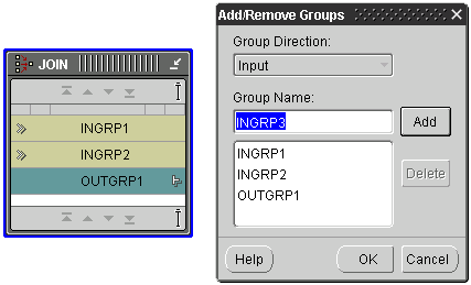
You can create a new attribute group in the mapping editor by right-clicking the name header and selecting Add/Remove Groups.
Figure 6-14 Add/Remove Groups Dialog
You cannot change the group direction. You add input groups to Joiners and output groups to Splitters. See «Adding Flow Operators to a Mapping» for more information.
To select multiple items from the selection box, hold down the Control key as you click each item. To select a group of items located in a series in the selection box, click the first object in your selection range, hold down the Shift key, and then click the last object in your selection range.
Editing Operator Attributes
For each mapping operator, you can add, remove, and rename attributes. After you have added or changed attributes or attribute groups, you must reconcile the mapping operators with their corresponding repository objects. See «Reconciling Mapping Operators with Repository Objects» for more information.
Adding or Removing Attributes
You can add attributes to or remove attributes from an operator on the Mapping Editor canvas.
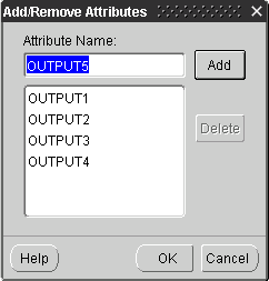
To add attributes to an Operator:
The Add/Remove Attributes dialog displays.
Figure 6-15 Add/Remove Attributes Dialog
To remove attributes from an operator:
The Add/Remove Attribute dialog displays.
To select multiple items from the selection box, hold down the Control key as you click each item. To select a group of items located in a series in the selection box, click the first object in your selection range, hold down the Shift key, and then click the last object in your selection range.
Renaming Attributes
You can rename mapping operator attributes.
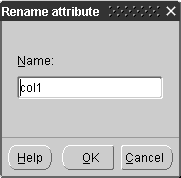
To rename an operator, attribute, or attribute group:
The Rename dialog displays.


