Volumetric lighting что это
GPU Gems 3
GPU Gems 3 is now available for free online!
The CD content, including demos and content, is available on the web and for download.
You can also subscribe to our Developer News Feed to get notifications of new material on the site.
Chapter 13. Volumetric Light Scattering as a Post-Process
Kenny Mitchell
Electronic Arts
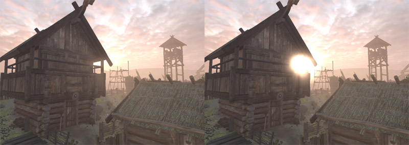
In this chapter, we present a simple post-process method that produces the effect of volumetric light scattering due to shadows in the atmosphere. We improve an existing analytic model of daylight scattering to include the effect of volumetric occlusion, and we present its implementation in a pixel shader. The demo, which is included on the DVD accompanying this book, shows the technique can be applied to any animating image of arbitrary scene complexity. A screenshot from the demo appears in Figure 13-1.
Figure 13-1 Volumetric Light Scattering on a Highly Animated Scene in Real Time
13.1 Introduction
In the real world, we rarely see things in a vacuum, where nothing exists between an object and its observer. In real-time rendering, the effect of participating media on light transport is often subject to low-complexity homogeneous assumptions. This is due to the intractable nature of the radiative transport equation (Jensen and Christensen 1998), accounting for emission, absorption, and scattering, in a complex interactive animated environment. In this chapter, we consider the effect of volumetric shadows in the atmosphere on light scattering, and we show how this effect can be computed in real time with a GPU pixel shader post-process applied to one or more image light sources.
13.10 References
Dobashi, Y., T. Yamamoto, and T. Nishita. 2002. «Interactive Rendering of Atmospheric Scattering Effects Using Graphics Hardware.» Graphics Hardware.
Hoffman, N., and K. Mitchell. 2002. «Methods for Dynamic, Photorealistic Terrain Lighting.» In Game Programming Gems 3, edited by D. Treglia, pp. 433–443. Charles River Media.
Hoffman, N., and A. Preetham. 2003. «Real-Time Light-Atmosphere Interactions for Outdoor Scenes.» In Graphics Programming Methods, edited by Jeff Lander, pp. 337–352. Charles River Media.
James, R. 2003. «True Volumetric Shadows.» In Graphics Programming Methods, edited by Jeff Lander, pp. 353–366. Charles River Media.
Jensen, H. W., and P. H. Christensen. 1998. «Efficient Simulation of Light Transport in Scenes with Participating Media Using Photon Maps.» In Proceedings of SIGGRAPH 98, pp. 311–320.
Karras, T. 1997. Drain by Vista. Abduction’97. Available online at http://www.pouet.net/prod.php?which=418&page=0.
Max, N. 1986. «Atmospheric Illumination and Shadows.» In Computer Graphics (Proceedings of SIGGRAPH 86) 20(4), pp. 117–124.
Mech, R. 2001. «Hardware-Accelerated Real-Time Rendering of Gaseous Phenomena.» Journal of Graphics Tools 6(3), pp. 1–16.
Mitchell, J. 2004. «Light Shafts: Rendering Shadows in Participating Media.» Presentation at Game Developers Conference 2004.
Nishita, T., Y. Miyawaki, and E. Nakamae. 1987. «A Shading Model for Atmospheric Scattering Considering Luminous Intensity Distribution of Light Sources.» In Computer Graphics (Proceedings of SIGGRAPH 87) 21(4), pp. 303–310.
13.2 Crepuscular Rays
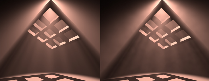
Under the right conditions, when a space contains a sufficiently dense mixture of light scattering media such as gas molecules and aerosols, light occluding objects will cast volumes of shadow and appear to create rays of light radiating from the light source. These phenomena are variously known as crepuscular rays, sunbeams, sunbursts, star flare, god rays, or light shafts. In sunlight, such volumes are effectively parallel but appear to spread out from the sun in perspective.
Rendering crepuscular rays was first tackled in non-real-time rendering using a modified shadow volume algorithm (Max 1986) and shortly after that, an approach was developed for multiple light sources (Nishita et al. 1987). This topic was revisited in real-time rendering, using a slice-based volume-rendering technique (Dobashi et al. 2002) and more recently applied using hardware shadow maps (Mitchell 2004). However, slice-based volume-rendering methods can exhibit sampling artifacts, demand high fill rate, and require extra scene setup. While a shadow-map method increases efficiency, here it also has the slice-based detractors and requires further video memory resources and rendering synchronization. Another real-time method, based on the work of Radomir Mech (2001), uses polygonal volumes (James 2003), in which overlapping volumes are accumulated using frame-buffer blending with depth peeling. A similar method (James 2004) removes the need for depth peeling using accumulated volume thickness. In our approach, we apply a per-pixel post-processing operation that requires no preprocessing or other scene setup, and which allows for detailed light shafts in animating scenes of arbitrary complexity.
In previous work (Hoffman and Preetham 2003), a GPU shader for light scattering in homogeneous media is implemented. We extend this with a post-processing step to account for volumetric shadows. The basic manifestation of this post-process can be traced to an image-processing operation, radial blur, which appears in many CG demo productions (Karras 1997). Although such demos used software rasterization to apply a post-processing effect, we use hardware-accelerated shader post-processing to permit more sophisticated sampling based on an analytic model of daylight.
13.3 Volumetric Light Scattering
To calculate the illumination at each pixel, we must account for scattering from the light source to that pixel and whether or not the scattering media is occluded. In the case of sunlight, we begin with our analytic model of daylight scattering (Hoffman and Preetham 2003). Recall the following:
Equation 1
where s is the distance traveled through the media and is the angle between the ray and the sun. E sun is the source illumination from the sun, ex is the extinction constant composed of light absorption and out-scattering properties, and sc is the angular scattering term composed of Rayleigh and Mie scattering properties. The important aspect of this equation is that the first term calculates the amount of light absorbed from the point of emission to the viewpoint and the second term calculates the additive amount due to light scattering into the path of the view ray. As in Hoffman and Mitchell 2002, the effect due to occluding matter such as clouds, buildings, and other objects is modeled here simply as an attenuation of the source illumination,
Equation 2
This consideration introduces the complication of determining the occlusion of the light source for every point in the image. In screen space, we don’t have full volumetric information to determine occlusion. However, we can estimate the probability of occlusion at each pixel by summing samples along a ray to the light source in image space. The proportion of samples that hit the emissive region versus those that strike occluders gives us the desired percentage of occlusion, D( ). This estimate works best where the emissive region is brighter than the occluding objects. In Section 13.5, we describe methods for dealing with scenes in which this contrast is not present.
If we divide the sample illumination by the number of samples, n, the post-process simply resolves to an additive sampling of the image:
Equation 3
13.3.1 Controlling the Summation
In addition, we introduce attenuation coefficients to parameterize control of the summation:
Equation 4
where exposure controls the overall intensity of the post-process, weight controls the intensity of each sample, and decay i (for the range [0, 1]) dissipates each sample’s contribution as the ray progresses away from the light source. This exponential decay factor practically allows each light shaft to fall off smoothly away from the light source.
The exposure and weight factors are simply scale factors. Increasing either of these increases the overall brightness of the result. In the demo, the sample weight is adjusted with fine-grain control and the exposure is adjusted with coarse-grain control.
Because samples are derived purely from the source image, semitransparent objects are handled with no additional effort. Multiple light sources can be applied through successive additive screen-space passes for each ray-casting light source. Although in this explanation we have used our analytic daylight model, in fact, any image source may be used.
In Figure 13-2, no samples from 1 are occluded, resulting in maximum scattering illumination under regular evaluation of L(s, ). At 2, a proportion of samples along the ray hit the building, and so less scattering illumination is accumulated. By summing over cast rays for each pixel in the image, we generate volumes containing occluded light scattering.
Figure 13-2 Ray Casting in Screen Space
We may reduce the bandwidth requirements by downsampling the source image. With filtering, this reduces sampling artifacts and consequently introduces a local scattering contribution by neighborhood sampling due to the filter kernel. In the demo, a basic bilinear filter is sufficient.
13.4 The Post-Process Pixel Shader
The core of this technique is the post-process pixel shader, given in Listing 13-1, which implements the simple summation of Equation 4.
Example 13-1. Post-Process Shader Implementation of Additive Sampling
13.5 Screen-Space Occlusion Methods
As stated, sampling in screen space is not a pure occlusion sampling. Undesirable streaks may occur due to surface texture variations. Fortunately, we can use the following measures to deal with these undesirable effects.
13.5.1 The Occlusion Pre-Pass Method
If we render the occluding objects black and untextured into the source frame buffer, image processing to generate light rays is performed on this image. Then the occluding scene objects are rendered with regular shading, and the post-processing result is additively blended into the scene. This approach goes hand in hand with the common technique of rendering an unshaded depth pre-pass to limit the depth complexity of fully shaded pixels. Figure 13-3 shows the steps involved.
Figure 13-3 The Effect of the Occlusion Pre-Pass
13.5.2 The Occlusion Stencil Method
On earlier graphics hardware the same results can be achieved without a pre-pass by using a stencil buffer or alpha buffer. The primary emissive elements of the image (such as the sky) are rendered as normal while simultaneously setting a stencil bit. Then the occluding scene objects are rendered with no stencil bit. When it comes to applying the post-process, only those samples with the stencil bit set contribute to the additive blend.
13.5.3 The Occlusion Contrast Method
Equally though, this problem may be managed by reducing texture contrast through the texture’s content, fog, aerial perspective, or light adaption as the intensity of the effect increases when facing the light source. Anything that reduces the illumination frequency and contrast of the occluding objects diminishes streaking artifacts.
13.6 Caveats
Although compelling results can be achieved, this method is not without limitations. Light shafts from background objects can appear in front of foreground objects, when dealing with relatively near light sources, as shown in Figure 13-4. In a full radiative transfer solution, the foreground object would correctly obscure the background shaft. One reason this is less noticeable than expected is that it can be perceived as the manifestation of a camera lens effect, in which light scattering occurs in a layer in front of the scene. This artifact can also be reduced in the presence of high-frequency textured objects.
Figure 13-4 Dealing with One Limitation
As occluding objects cross the image’s boundary, the shafts will flicker, because they are beyond the range of visible samples. This artifact may be reduced by rendering an extended region around the screen to increase the range of addressable samples.
Finally, when facing perpendicular to the source, the light’s screen-space location can tend toward infinity and therefore lead to large separation between samples. This can be diminished by clamping the screen-space location to an appropriate guard-band region. Alternatively, the effect can be faded toward the perpendicular and is further decreased when using an occlusion method.
13.7 The Demo
The demo on this book’s DVD uses Shader Model 3.0 to apply the post-process, because the number of texture samples needed exceeds the limits of Shader Model 2.0. However, the effect has been implemented almost as efficiently with earlier graphics hardware by using additive frame-buffer blending over multiple passes with a stencil occlusion method, as shown in Figure 13-5.
Figure 13-5 Crepuscular Rays with Multiple Additive Frame-Buffer Passes on Fixed-Function Hardware
13.8 Extensions
Sampling may occur at a lower resolution to reduce texture bandwidth requirements. A further enhancement is to vary the sample pattern with stochastic sampling, thus reducing regular pattern artifacts where sampling density is reduced.
Creating a balance between light shaft intensity and avoiding oversaturation requires adjustments of the attenuation coefficients. An analytic formula that performs light adaption to a consistent image tone balance may yield an automatic method for obtaining a consistently perceived image. For example, perhaps we can evaluate a combination of average, minimum, and maximum illumination across the image and then apply a corrective color ramp, thus avoiding excessive image bloom or gloominess.
13.9 Summary
We have shown a simple post-process method that produces the effect of volumetric light scattering due to shadows in the atmosphere. We have expanded an existing analytic model of daylight scattering to include the contribution of volumetric occlusion, and we have described its implementation in a pixel shader. The demo shows that this is a practical technique that can be applied to any animating image of arbitrary scene complexity.
Hx Volumetric Lighting
Hx Volumetric Lighting is a Unity asset that enables volumetric dynamic lighting in your scene, adding depth and realism with rays of light and fog of variable density. It’s easy to use and runs efficiently.
Features
Documentation
Hx Volumetric Lighting is the easiest way to get high quality volumetric lighting in your Unity scene. Follow this guide to get started, and let us know if you have any questions or comments.
Requirements
Take these requirements under consideration when using Hx Volumetric Lighting:
Setup
If you are not using HDR rendering on your camera, the volumetric effect will automatically be converted to LDR. If you are using HDR, It is recommended that you use tone mapping. Otherwise, you can enable the Map To LDR setting in the Advanced Settings section, and it will handle tone mapping for you. However, it is recommended that you use an external tone mapper.
Settings
In your camera’s inspector window, you can adjust several parameters to control the volumetric effect.
Light Scattering Settings
These set the default values for the lights. You can overwrite them on a per-light basis by selecting custom settings in the inspector window for each light, although it is recommended to use this sparingly, as conflicting extinction values can cause some artifacts for overlapping lights.
Density
A higher density value will result in more visible light scattering, but will also make your scene more foggy.
Mie Scattering
This value describes the angular light scattering amount. A low value will scatter the light evenly in all directions, while a high value will scatter the light more in the direction of the light. At high values, being in the direct path of the light direction and looking directly at the light source will give you a blown out, staring-into-the-sun effect.
From left to right, lower to higher values of Mie scattering with a point light.
Lower to higher values of Mie scattering with a spot light.
A side view of the same lights as the spot light above.
Ambient Lighting Strength
Ambient light can soften up your scene.
This is the same scene with ambient lighting turned off. Click on each image to enlarge them and compare.
Extinction
Extinction describes the brightness of the scattered light. A higher extinction value causes the light to fade more as it travels through dense air.
Extinction Effect
This darkens the rendered pixel color based on the air density and the extinction amount. This only works if a volumetric directional light is in the scene.
Sun Size
This value allows you to create a sun-like effect when looking directly at a light source. This effect can look bad if you have a low sample rate or are rendering at quarter resolution.
Sun size is at 0 on the left, and 1 on the right, creating a sun effect.
Fog Height Settings
The height fog feature modifies the fog amount based on height. You can use this to achieve a ground-based fog effect.
A scene with fog height enabled, giving the effect of extra density on the ground.
Height Fog Enabled
Select this to activate fog height.
Fog Height
The fog above this height is scaled by the Above Fog Percent value.
Fog Transition Height
The fog below this height is equal to the global air density (the same amount as if Height Fog is not activated). The fog between this value and the Fog Height linearly transitions from the global air density to the value scaled by the Above Fog Percent.
Above Fog Percent
This percentage scales the fog amount for fog above the Fog Height. Choose a value between 0 and 1.
Noise Settings
3D Noise can be added to the air density, which makes the air look less homogeneous.
The right image has a subtle amount of noise enabled.
Noise Enabled
Select this to enable the 3D noise.
Noise Scale
This adjusts the scaling of the noise to alter the amount of detail to the noise.
Noise Velocity
You can add movement to the noise by adjusting this vector, which controls the direction and magnitude of the movement.
Particle Density Settings
You can control the air density in an area simply by using particle emitters with a HxVolumetricParticleSystem.cs script attached. In that script, you can set the particle density, which uses the alpha channel of the main texture. You can disable the renderer on the emitter if you only want to modulate the fog value without drawing the particle.
The left image shows particle emitters modulating the air density, while the right image has the feature disabled.
Particle Density Support
Check this to enable support for particle density.
Density Resolution
The particle density feature uses a 3D grid that the emitters render into. This setting controls the scale of the 3D grid, letting you make a tradeoff between speed and detail. It will not render out to a higher value than the Resolution setting in General Settings.
Density Distance
This parameter specifies the distance of the last slice of the 3D grid. If you have a 2.5D game without much depth, you can reduce this value to get more detail, since it is not stretched as far.
Transparency Settings
Objects with transparent shaders can be modified to work with Hx Volumetric Lighting. Like the particle density feature, the volumetric lighting will be rendered into a 3D grid with which transparent objects can sample when compositing. Included in this package are modified versions of the standard Unity shaders that allow for transparency with this system. When you select a shader for your material, you can find the modified standard shader under HxVolumetric->Standard.
Transparency support is enabled in the left image, allowing for proper rendering of the windows. When compositing transparent objects into the scene, extra information needs to be rendered out in a 3D texture, otherwise it doesn’t know how much volumetric lighting is in front and behind it.
Transparency Support
Check this to activate support for transparency.
Transparency Distance
This is the distance of the last slice in the grid. Like the particle density grid, if you have a 2.5 game without much depth, you can reduce this value to get more detail.
Blur Transparency
This setting blurs transparent areas, removing grainy effects. It will introduce some bleeding. The recommended setting is 1.
Transparency blur is enabled in the left image, and disabled in the right image.
Enabling transparency support in custom shaders
If you are using a custom shader, you will need to make some minor modifications in it to get transparency working. Modified versions of the Unity shaders are included in this package, which you can find under HxVolumetric->Standard.
Modify your shader by adding this line to the top:
Add this line to each transparent pass:
You will need data to reconstruct the world position. If you don’t have it, add this definition to the vertex shader struct, substituting n for the number of the next free TEXCOORD in your vertex struct:
Then add this to your vertex shader:
In your fragment shader, in the first pass, modify your final output with this code:
In any additional passes, use this code:
General Settings
Resolution
This is the resolution that the volumetric lighting is rendered at. Quarter resolution is recommended for a mid-range GPU.
Sample Count
You can adjust the amount of samples used in the raymarching step of the lighting system. Higher values will give better signal fidelity, although with a tradeoff in framerate.
Directional Sample Count
This controls the raymarching sample count for direction lights, since you generally want a higher sample count for a directional light compared to a spot or point light.
Max Directional Ray
This is the maximum distance from the camera that should be sampled for directional lights. Limiting this distance can reduce over-fogging at large distances.
Max Light Distance
This is maximum distance that point lights and spot lights are rendered. Their intensity fades out near the edge of this distance. You can adjust this to disable the volumetric effect on distant lights for a performance increase, although distant lights are already much cheaper to render than closer lights.
Advanced Settings
Blur Count
This is the amount of depth-aware blur passes. More passes will give better results, but it is an expensive operation. One to two is normally enough.
Blur Depth Falloff
This value is used in the depth-aware blur passes. A lower value will give more even results but will cause bleeding over the edges, giving a bloom-like effect. A higher value will retain object silhouettes, but will result in harsher artifacts. Choose a value appropriate for your art style.
Downsampled Blur Depth
If you are rendering at lower resolutions, this value will be used as the depth falloff.
Upsampled Blur Count
If you are rendering at lower resolutions, it will do a final blur pass to clean up edge artifacts. It’s a bit computationally expensive, so set it to 0 if you are okay with edge artifacts.
Depth Threshold
If the depth is within this threshold when upsampling, the result will be bilinearly sampled.
Gaussian Weights
Select this to use a Gaussian weighted blur. This will make the volumetric effect less blurry, but can also make it more splotchy.
Map to LDR
If you are not using HDR on your camera, this option will handle tone mapping for you, although it is recommended that you use an external tone mapper.
Here are some best practices for improving your run-time performance.
Road Map
These are features which we plan to add in the future:
About
Hx Volumetric Lighting is created by Hitbox Team. It is part of the lighting system used in the upcoming game, Spire. You can contact us in the following ways:


